 |
 |
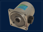
| Motor |
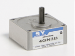
Gear Box |
| 4IK25GK-ST1 |
4GK3B |
| * |
Motor |
4IK25GK-ST1 |
| * |
Gear Box |
4GK3B |
| Gear Type: |
|
| Gear Ratio Selection: |
|
|
|
|
|
Option : P
| |
|
P: |
Contains a built-in thermal
protector. When a motor overheats for any
reason, the thermal protector is opened and the
motor stops, and the power supply to the
electromagnetic brake is kept and the brake is
released. When the motor temperature drops, the
thermal protector closes and the motor restarts.
Be sure to turn the motor off before inspecting. |
| |
|
:: Motor Specifications
| Frame Size |
Wiring Type |
Output Power |
Voltage |
Frequency |
Current |
Starting Torque |
Rated Torque |
Rated Speed |
Capacitor |
| [mm] |
|
[W] |
[V] |
[Hz] |
[A] |
[Kgfcm] |
[Kgfcm] |
[r/min] |
[μF] |
| 80 |
Lead wire |
25 |
Three-phase
200 |
50 |
0.25 |
2.4 |
1.9 |
1300 |
0 |
| 80 |
Lead wire |
25 |
Three-phase
220 |
60 |
0.25 |
1.6 |
1.6 |
1650 |
0 |
| 80 |
Lead wire |
25 |
Three-phase
230 |
50 |
0.2 |
1.6 |
1.6 |
1300 |
0 |
|
:: Gear Box Specifications
| Gear Type |
Gear Ratio |
Direction of Rotation |
Frequency |
Speed |
Permissible Torque |
Permissible Overhung Load |
Permissible Thrust Load |
| from the tip of the shaft 10mm |
from the tip of the shaft 20mm |
| |
|
|
[Hz] |
[r/min] |
[Kgfcm] |
[Kgfcm] |
[Kgfcm] |
[Kgfcm] |
| Parallel Shaft |
3
|
Same direction as the motor shaft |
50
|
500 |
4.61
|
10 |
15 |
5 |
| Parallel Shaft |
3
|
Same direction as the motor shaft |
60
|
600 |
3.88
|
10 |
15 |
5 |
| Parallel Shaft |
3
|
Same direction as the motor shaft |
50
|
500 |
3.88
|
10 |
15 |
5 |
● |
The speed is calculated by dividing the motor's synchronous speed (50 Hz: 1500 r/min, 60 Hz: 1800 r/min) by the gear ratio.
The actual speed is 2 to 20% less than the displayed value, depending on the size of the load. |
● |
The actual speed is 2 to 20% less than the displayed value, depending on the size of the load.
|
|
:: Characteristics/Dimensions/Wiring Diagrams
|
:: Safety Standards
| 適用規格 |
適用機關 |
規格代號 |
| EN 60335-1 |
SGS |
ELC00538 |
|
:: Motor General Specifications
|
Insulation Resistance |
100M
ohms or more when measured by a 500 VDC megger between the windings
and the frame after rated motor operation under normal ambient
temperature and humidity. |
|
Dielectric Strength |
Sufficient to
withstand 1.5 kV at 50 Hz and 60 Hz applied between the windings and
the frame for 1minute after rated motor operation under normal
ambient temperature and humidity. |
|
Temperature Rise |
144°F (80°C) or
less in the coil, as measured by the resistance change method after
rated operation with a gearhead installed. |
|
Insulation Class |
Class F (302°F
[150°C]) |
|
Overheat Protection |
Built-in thermal
protector (automatic return type) Open: 266°F ± 9°F (130°C ± 5°C)
Close: 179.6°F ± 27°F (82°C ± 15°C) |
|
Ambient Temperature |
14°F ~ 104°F (-10°C ~ +40°C) (nonfreezing) |
|
Ambient Humidity |
85% maximum (noncondensing) |
|
:: Accessories (included)
|
Model |
Quantity |
Product/Description/Standards |
PDF |
| Capacitor
|
1 |
For
single-phase Motor |
CAD |
| Screw |
4 |
Screw |
CAD |
| Key |
4 |
Key |
CAD |
| Leading
Wire |
1 |
length 20cm |
CAD |
| Motor with Fan
|
1 |
link the Motor shaft ,for
over 60W Motor |
CAD |
|
Sheath of Shaft
|
1 |
Fpr protect
external shaft |
CAD |
| |
|
|
|
|
:: Accessories (sold separately)
|
Model |
Product/Description/Standards |
PDF |
| Mounting Brackets |
Motor/GearBox Mounting
Brackets/For Frame Size have 60mm、80mm、90mm、104mm Material:stainless steel
|
CAD |
| Leading
Wire |
length 30cm |
CAD |
| Leading
Wire |
length 50cm |
CAD |
| Leading
Wire |
length 100cm |
CAD |
| Independent Fan
|
Motor with Independent Fan,for over 60W Motor |
CAD |
|